International Customers:
Click Here | Contact Us

The goal when developing our new top mounted intercooler was to make it the very best aftermarket top mounted intercooler for WRX/STi... period.
We studied our competitors products and fixed all of the mistakes they have made...some of them major.
The most obvious error that EVERY one of our competors makes is not supplying their intercooler with proper ducting/shrouding to suit the increased size of the new intercooler. There is no point in installing a larger intercooler and leaving the factory under bonnet splitter/shroud in place. Here is the solution. A properly sized splitter/shroud to suit the application.
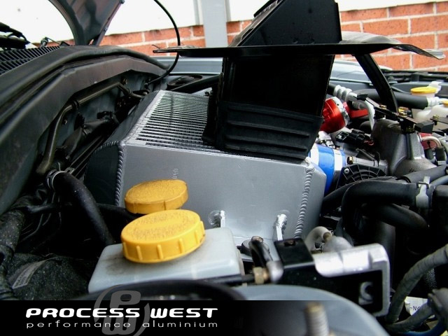
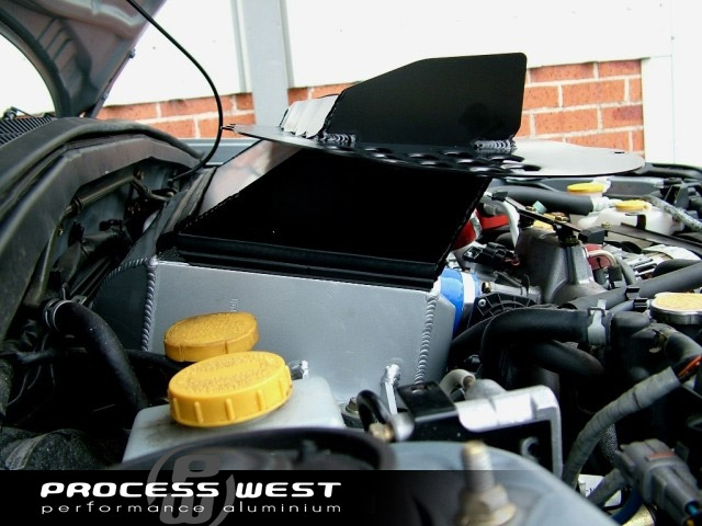
Pictured below is a pic of our top mounted intercooler installed in a 2006 Forester XT. For demonstration purposes we have removed the factory splitter/shroud and placed it on the intercooler as if the bonnet were shut. Its simple to see that 50% of the new upgraded intercooler would be seeing no ambient air flow... total waste of time and money. The picture (below right) is how it should be done. Process West intercooler and splitter/combination showing 100% of the new larger intercooler with full ambient airflow over the entire core.


 |
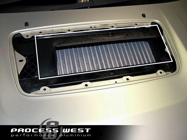
This image (left) shows a 2005 WRX with the bonnet scoop removed, factory splitter/shroud still in place. The white line shows the actual dimension of the upgrade intercooler underneath. Again...you can see the pointless exercise in upgrading the intercooler and not the ducting. |
The next major problem that we see competitors doing (and they all copy each other) is building an intercooler that is too thick. Their design criteria is spot on for bragging rights whilst marketing. They say that bigger is better. This is totally not the case with an intercooler that is mounted at 90 degrees to the ambient air flow.
For good heat exchange to take place you need good ambient airflow through the intercooler. In the case of the boxer engine with its intercooler mounted under a bonnet scoop the ambient airflow speed is already struggling after doing a 90 degree turn through the scoop. The last thing it now needs to do is find its way through 114mm (4.5in) of intercooler core. This will result poor heat exchange and high inlet temps.
Our intercooler is 90mm thick (3.5in) and in turn the intercooler breathes, gives lower outlets temps and in turn more power.
Almost all of the aftermarket Y-pipes we see do not distribute the charge air flow along the intercooler evenly. Their Y-pipe usually consists of one nicely flowing section with an afterthough spout as the second duct.
Looking at the picture (below left) it's easy to see that our Y-pipe will give perfect charge air distribution. Combining all 3 features of out top mounted intercooler gives the perfectly designed top mounted intercooler for Subaru. This picture (below right) shows the complete combination of Y-pipe (underneath), intercooler and splitter.


Before looking at the results below I must say that dynos and top mounted intercoolers are not a great mix. No matter where you position the dyno fan there is still very little air flow into the bonnet scoop. Having said that both the stock intercooler and the PW upgrade intercooler were subject to exactly the same test conditions.
A few other things worth mentioning. The test vehicle was a stock (apart from a BPM GT exhaust system) 05 WRX. Stock WRXs consistently put down about 90kw ATW on his dyno. The intercooler outlet temp probe was placed in the silicon hose joiner at the throttle body. (IAT on the data sheet).
We started off with the PW intercooler/splitter and did a base line power run. Result was 115.5kw. Looking at the intercooler outlet temp saw a peak of 51C. I must say at this point I was a little disappointed. We saved all of the data collected during the run so that we could overlay it with the results from the stock intercooler.
Next we installed the stock intercooler/splitter. Max power was 107.5kw. More disturbing was how badly the factory WRX intercooler performs.
 |
This graph (pictured left) shows the before and after power. Note the test number. These 2 runs were back-to-back. |
 |
This graph (pictured left) shows the before and after intercooler outlet temps. Dark line is the PW unit, lighter line the stock unit. Note, we made sure that we started the test with same intercooler outlet temp to give an accurate comparision between the two. You can see both intercoolers started at about 37C. The PW unit saw a max of 51C and the stock unit 66C. This, of course is after one run on the dyno. |
 |
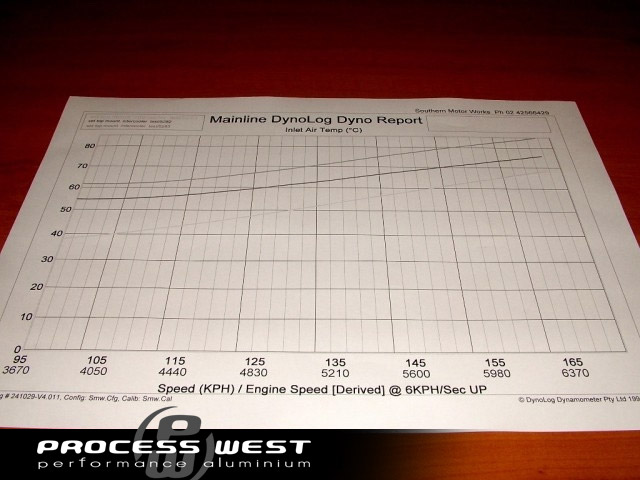
Next test was to see how badly the stock intercooler is effected by constant back-to-back runs. The graph (pictured left) shows 3 runs in quick succession. After the 3rd run we were up to 84C intercooler outlet temp. I would hate to see the outlet temps after a few laps at the circuit. |
Ok, real testing is done on the road. The only data that I was able to get on the road (with the equipment that I have) is intercooler outlet temps. I used a Fluke 87 digital multimeter with a K-type thermo couple just before the throttle body. (same position a the dyno test). Im not able log this data so you will just have to take my word for it.(Hence the reason stage 2 testing that will be done)
While doing the dyno testing I compared my Fluke meter with the dyno AIT probe and they were always within a degree of each other.
So, out into mountains with the PW intercooler/splitter combo. Basically I was unable to get the intercooler outlet temp above 43C no matter how hard I pushed. Great... now Im happy. Back to workshop and changed back to the stock intercooler/splitter.
Went and did the same hard driving and saw a peak of 72C which would probably have kept rising but I decided that was enough. The car also felt a lot less lively.